Redesigning the motor mounts on vtol clubs 2026 drone
Skills: Mechanical Design, Structural Analysis with FEA, Manufacturing with Waterjet & Milling
As Chief Engineer of the VTOL CWRU club at Case Western Reserve University, I have been facilitating the design and fabrication of our 2026 Vertical Takeoff and Landing (VTOL) drone. Despite my leadership role, I have remained deeply involved in the technical design decisions throughout the project. One of my recent focus areas has been the redesign of the motor mounts, with the goal of improving the performance and responsiveness of the aircraft.
This year, due to the requirement for autonomous pickup and delivery of firefighting payloads, our design priorities have centered on responsiveness and controllability. The motor mounting system was therefore optimized with respect to both the blade passing frequency and changes in the motor thrust control loop. The blade passing frequency is determined by the maximum motor speed of 7030 RPM, which corresponds to 117 Hz. Because the propellers have two blades, the effective blade passing frequency is 234 Hz. This frequency represents force oscillations caused by motor or propeller imbalance. If the structure has a natural frequency near this value, these oscillations can be amplified, potentially leading to structural or control issues.
Last year’s design utilized a cantilevered motor mount that extended beyond the edge of the arm. While this configuration allowed for easy access to the mounting hardware, the cantilevered geometry resulted in increased deflection under the vertical lift forces generated by the motor. This reduced stiffness and lowered the natural frequency of the structure. The redesigned mount, shown in the first three figures, eliminates the cantilever in favor of a significantly stiffer configuration that is constrained on both sides by bolted connections. These connections still allow for straightforward disassembly of the motor from the mount. The mounting rings that attach to the motor mount are bonded directly to the drone’s carbon fiber arms.
Overall, the redesign reduced mass by 13% and decreased deflection by an order of magnitude. The resulting natural frequency increased by nearly a factor of four, ensuring the structure remains well separated from blade passing frequencies and control loop excitation, thereby improving responsiveness and stability.
After completing an initial test cut of the new design using the university waterjet machine, the next steps include validating post-processing operations such as face milling, drilling, and hole tapping. Following successful testing, we will order the required stock material to manufacture mounts for all six arms and develop a standard operating procedure (SOP) to ensure consistent assembly and that final parts meet design intent.
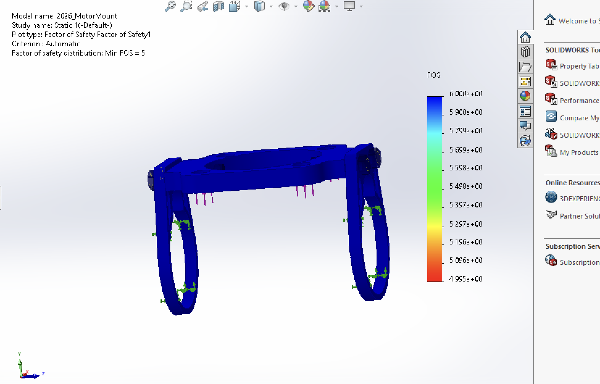
Fig 1. FOS plot from new mount design
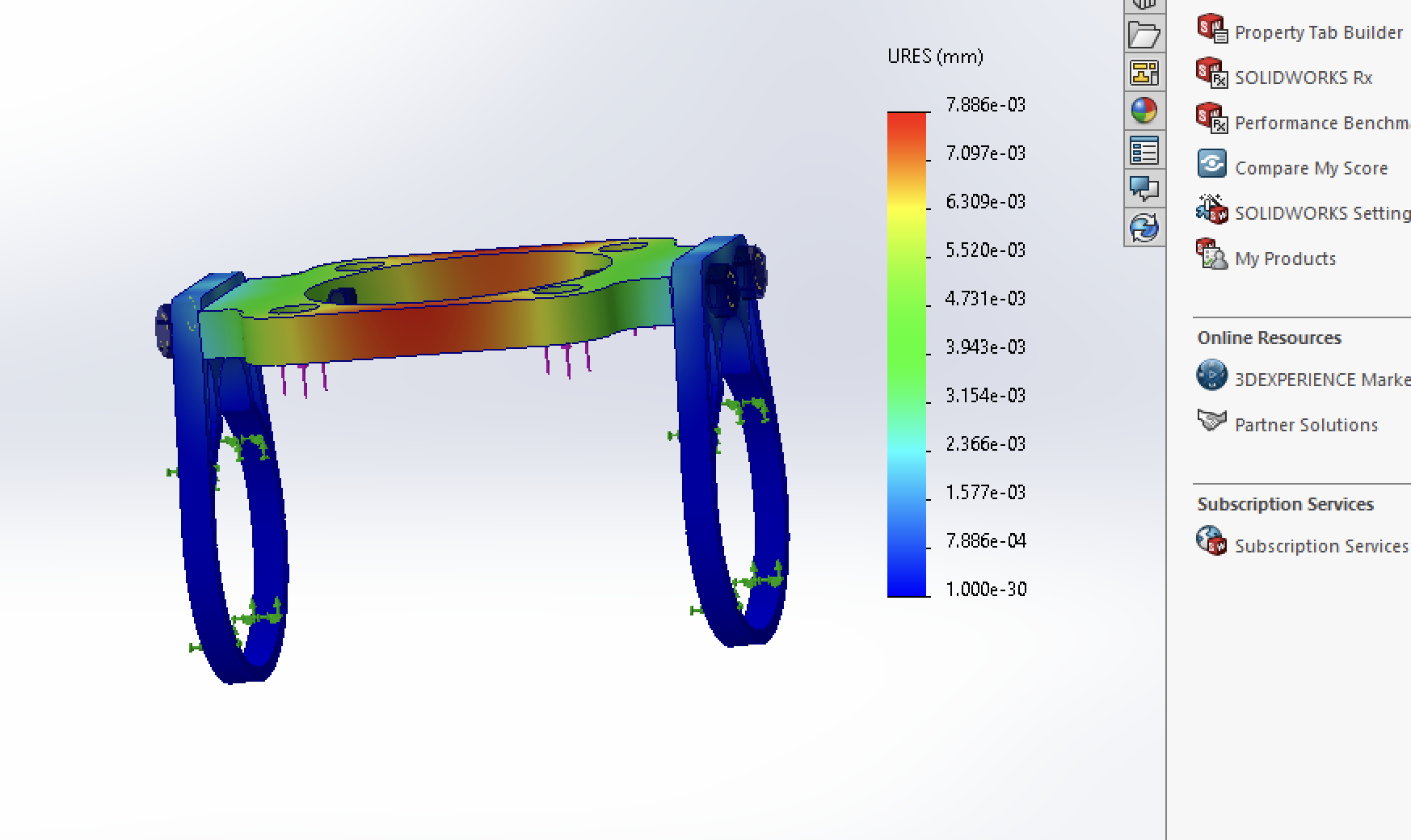
Fig 2. Deflection plot of the new mount design
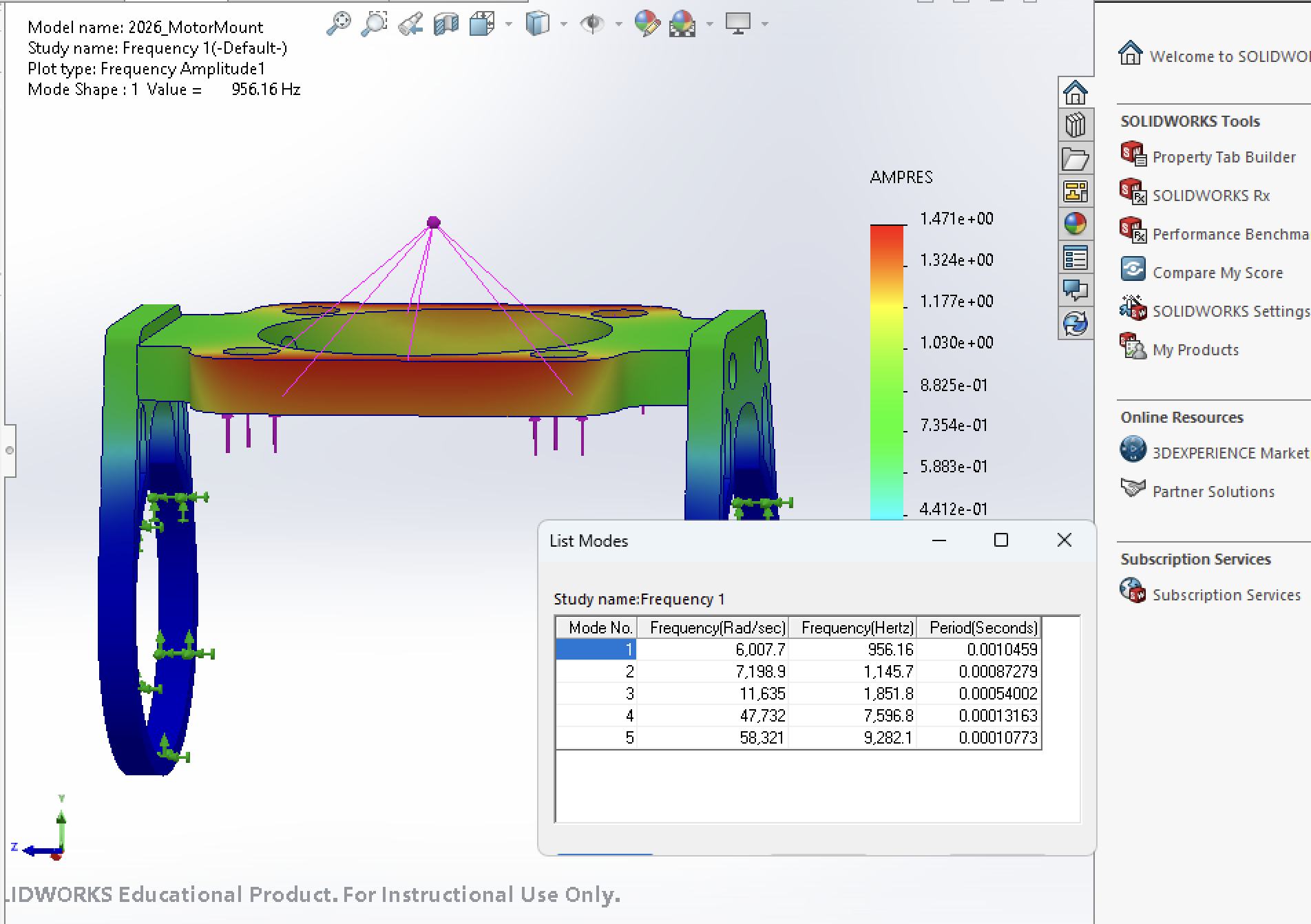
Fig 3. Natural frequency plot of new motor mount
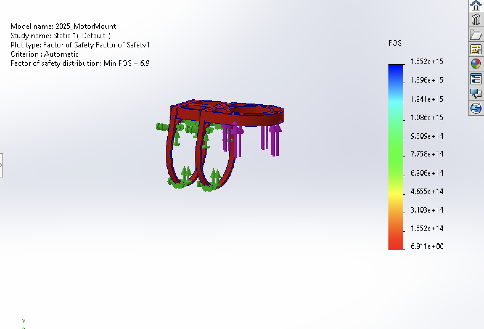
Fig 4. FOS plot for 2025 motor mount design
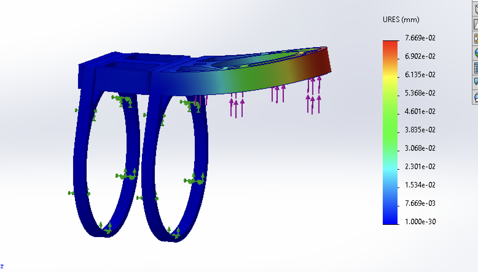
Fig 5. Deflection plot for 2025 motor mount design
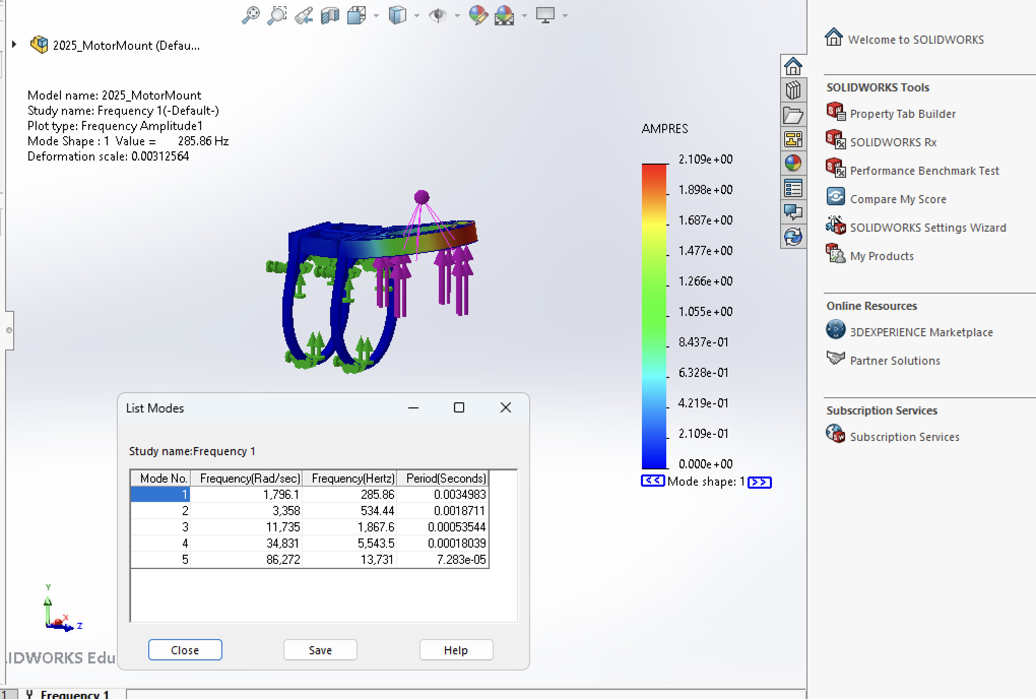
Fig 6. Natural frequency plot for the 2025 motor mounts
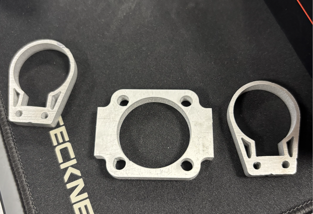
Fig 7. Completed test cut on the waterjet of the new design
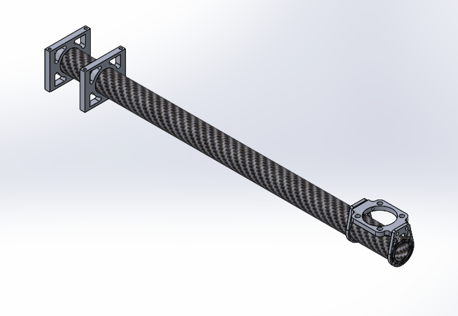
Fig 8. New arm assembly for this years drone