Team lead of designing a motorcycle engine for coursework
During the Fall 2025 semester at Case Western Reserve University, I stepped up to serve as the team lead of a 10-person group tasked with designing a motorcycle engine with a total displacement between 1.5 and 1.8 liters (which, yes, is very oversized for motorcycle use—but that was the requirement). Our design optimized cost of manufacturing, fuel efficiency, and other performance parameters.
I divided our team into three distinct groups: CAD/Design, Simulations, and Manufacturing. As team lead, I was responsible for overseeing the technical decisions that went into the design. This required close coordination with each group as they worked, ensuring that developments were communicated quickly so all teams remained aware of one another’s progress.
I found this experience to be incredibly valuable for developing my project management and leadership skills. I directed the design of a 200+-part CAD assembly; oversaw analyses of thermal systems, engine balancing, and structural safety requirements; and evaluated the cost-effectiveness of materials and manufacturing methods. Additionally, I coordinated weekly technical presentations, midterm and final presentations, and a 285-page report submitted at the end of the term.
This experience consistently challenged me, but it is in these situations that I learn the most and grow as an engineer. Overall, I am proud of both myself and my team for being one of the groups to earn an A on the project.
CAD design REsponsibilities
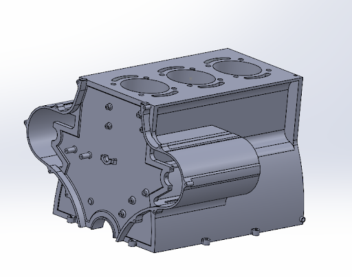
With my strong background in design work using SOLIDWORKS and a passion for automotive engineering, I took on tasks to design many of the parts for our team. Above is the engine block that I designed for our team, where I had to take into account lubrication and coolant channels, weight minimizing, and manufacturability.
The coolant jackets I designed fully enclose the cylinder housings in the engine block, but funnel up to the six curved slots seen in the picture above. These slots were designed to a 10 mm thickness, which provided us with the best results in our thermal analysis, giving us an external wall temperature of 90 degrees Celsius.
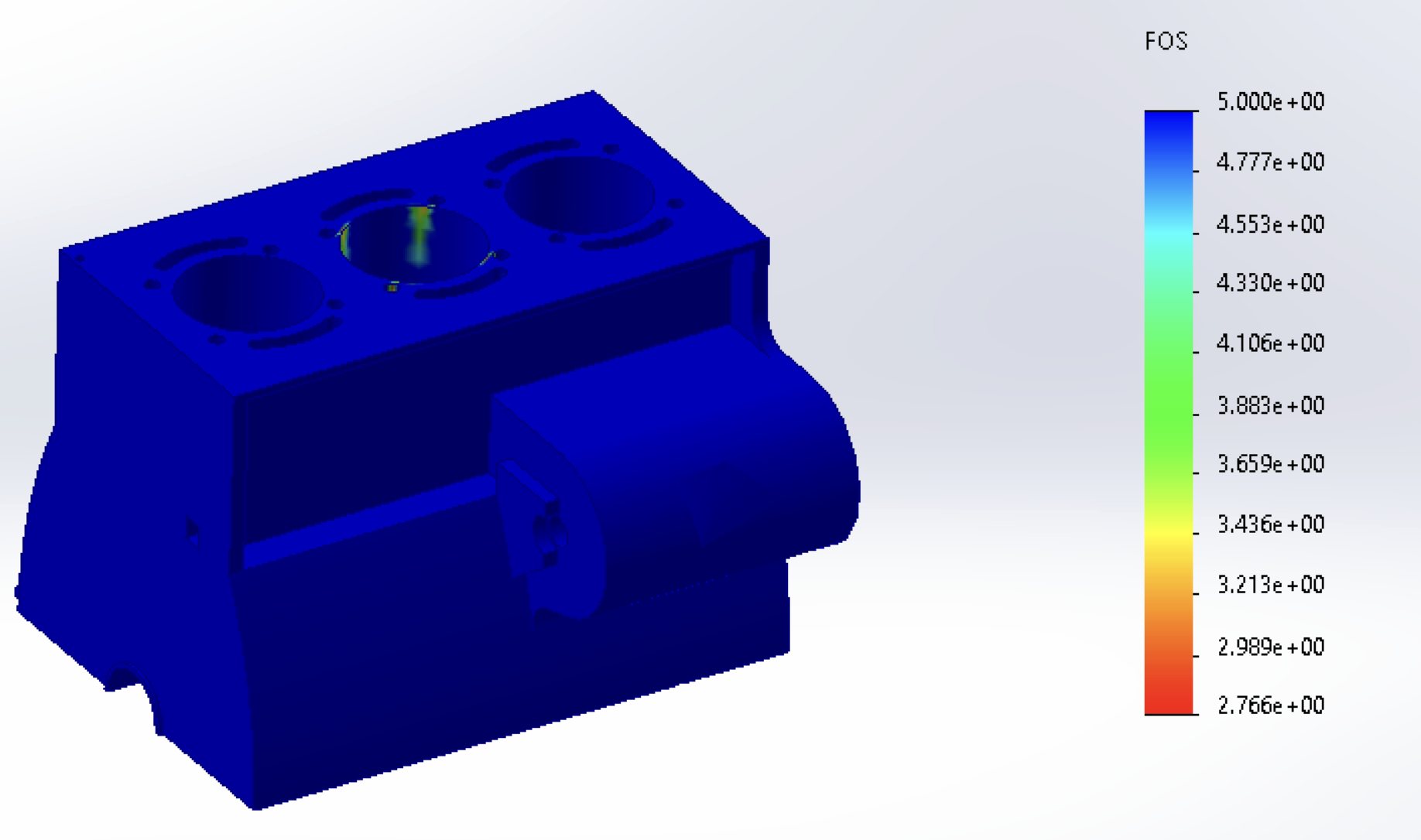
As can be seen below, I performed an FEA analysis on the engine block to test the factor of safety when facing the combustion forces, peaking at 8000 kPa inside the combustion chamber. To achieve the most accurate result, I included the temperature of the inside wall of the combustion chamber, a temperature at 30 mm distance away from the combustion chamber, and the outer wall temperature. This accounts for the decreased strength that aluminum alloy experiences as it heats up.
The results of FEA showed weakness at the threaded holes for the cylinder head bolts, which I also designed. Through design iterations, I settled on the hole locations below, given their reasonable factor of safety of 2.7 and showing no signs of fatigue failure in further analysis.
In the gallery of photos below, you can see the lubrication channels that I designed, which inlet at a corner and first split towards the main bearings in the engine block, and then branch upwards towards the cylinder head. For all these channels, I held them as far from the center of the engine block, and therefore avoided heating the oil until it reached the intended bearings.
Additionally you can see the pent roof combustion chamber I designed using surface modeling in Figure 7 below.
ANalysis Responsibilities
Throughout the semester, I also enjoyed learning and developing my MATLAB and analysis skills by working with our simulations team. For our project, we were assigned to work through an analysis of our Otto cycle, both ideal and not ideal, in order to find our horsepower and torque curves. Additionally, we did thermal analysis by setting up the thermal circuit of our engine, and found the mass flow entering the intake port, and exiting through the exhaust port.
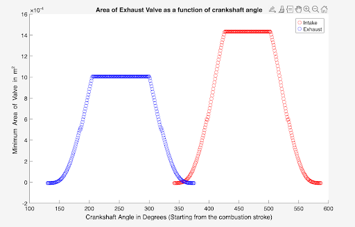
One of my main projects was developing a MATLAB script to determine the valve area of our intake and exhaust valves as a function of the crankshaft angle, as well as the mass flow through the valves. To determine the formulas for this, I researched textbooks to identify the different stages that define different valve areas. The fundamental behind this method is that because the valve area is defined as a curtain area, gas must make a turn around the valve to enter the port.
This led me to begin writing my MATLAB script that transferred the crank angle of the engine to the angle of the camshafts, which can be translated to the lift of the valves. This was then plotted on a dot graph, first with the exhaust valve, blue in the picture above, and then the intake valve area, which was shown to overlap by 37 degrees from exhaust to intake. This principle allowed our engine to take advantage of scavenging, where the momentum of the exhaust gases leaving the combustion chamber provides a vacuum effect that pulls new intake air in.
After modeling the valve areas, I used them to write a script that analyzed the mass flow. Again, doing my due diligence through research of engine design textbooks, I found an equation for mass flow rate, which depended on the pressure difference between the combustion chamber and the intake or exhaust manifold. For the intake stroke, the intake manifold maintains a steady pressure of about 1 atmosphere, while the rapid downwards motion of the piston creates a vacuum effect, since the volume is increasing, therefore the pressure decreases. To get the most accurate representation, though, I integrated with time steps to determine the amount of mass that has entered the system in the past time step, and adjusting the PV = nRT equation according to this.
For the intake stroke, I modeled an isothermal process, but for the exhaust stroke I modeled both variable mass, and variable temperature to account for the large temperature change as exhaust gases rush out of the combustion chamber.
Overall, my work with the analysis of our engine was exciting work for me, as I developed my skills with MATLAB, and learned further about the fluid and thermal systems in engines.
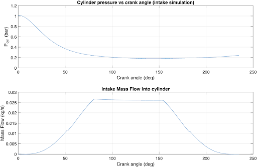
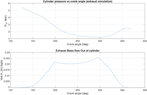
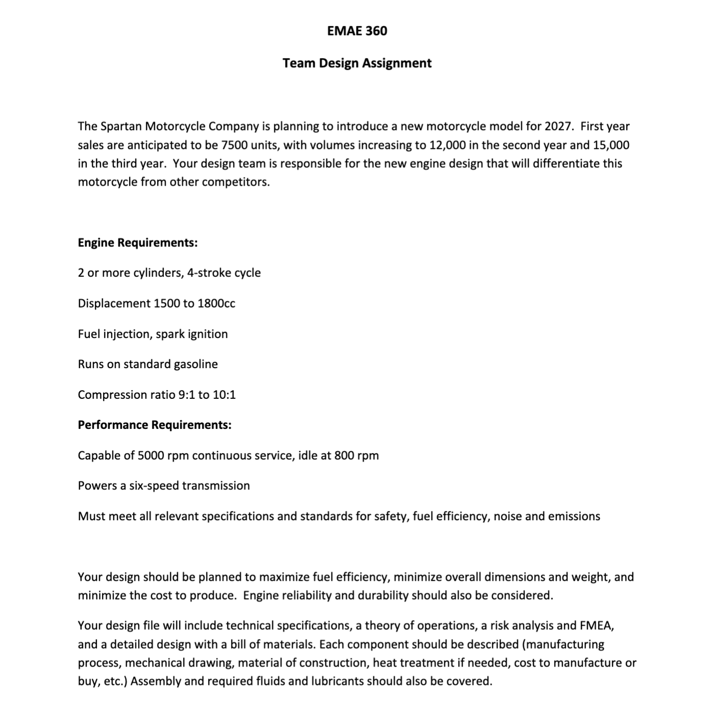
Fig 1. Assignment description for the course
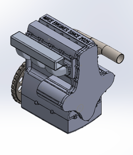
Fig 2. Isometric view of the full engine assembly as presented in our final presentation.
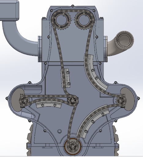
Fig 3. View of the balance and timing assembly that I designed and did analysis for
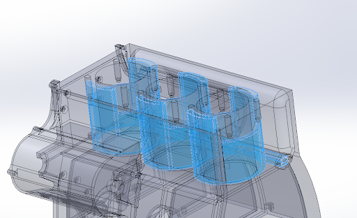
Fig 4. Design of coolant channels within the engine block
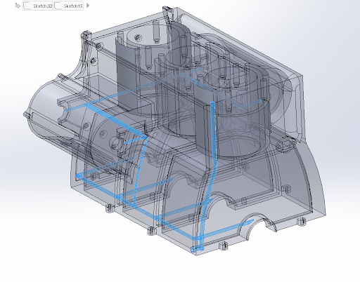
Fig 5. Lubrication channels designed for the oil flow through engine block and up towards cylinder head
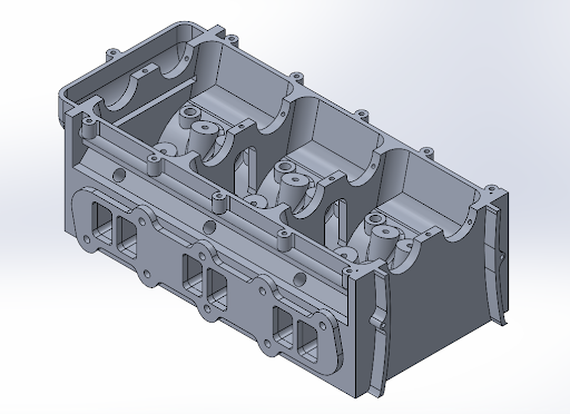
Fig 6. View of design for the cylinder head
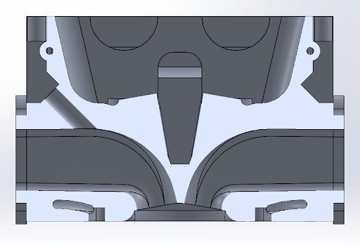
Fig 7. Cross sectional view of the cylinder head showing intake and exhaust ports, pent roof design, coolant exit channels, and mounting hole for port injector
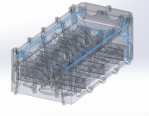
Fig 8. Design of lubrication channel for the cylinder head