2025-2026 VTOL Drone
This year I was elected Chief Engineer for the VTOL club at Case Western Reserve University where I led two subteams (Mechanical/Aerospace and Electrical Engineering), in designing an autonomous flight optimized hexacopter to complete a payload retrieval and target drop mission at the Vertical Flight Society Design Build Vertical Flight competition. At competition in April, our aircraft consistently completing missions in up to 20 mph winds scoring in the range of 210-240 points (out of 300 maximum). Overall, our team earned the third highest mission score, a rewarding result for our team, which worked incredibly hard throughout the year.
Primary skills and experiences:
MATLAB programming for simulating drone flight
Structural analysis and optimized design around stiffness and natural frequency
Project management skills working with a cross-functional team to integrate mechanical, electrical and software systems to meet deadlines
Working with flight planning software, QGroundControl, to plan missions, collect flight data from flight tests, and calibrate flight controller sensors
Planning different manufacturing procedures for water-jetting, post-processing of parts, epoxy bonding and 3D printing
You can find more detailed breakdown of my work in the text below the pictures!
Video of our aircraft autonomously flying to a 3 ft x 3 ft target to drop fire-retardant payloads to simulate forest fire relief.
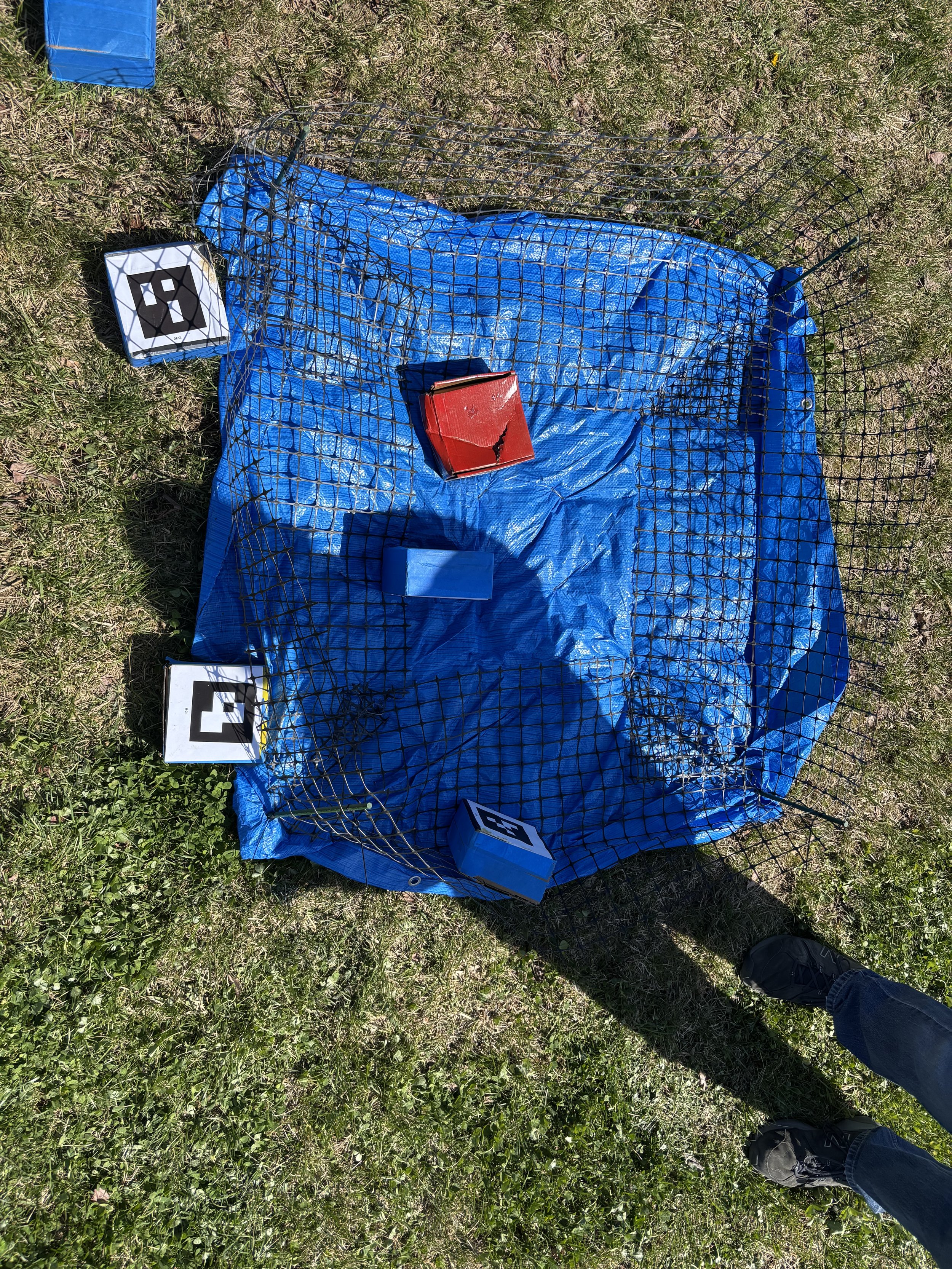
Final payload location at the end of one of our mission attempts
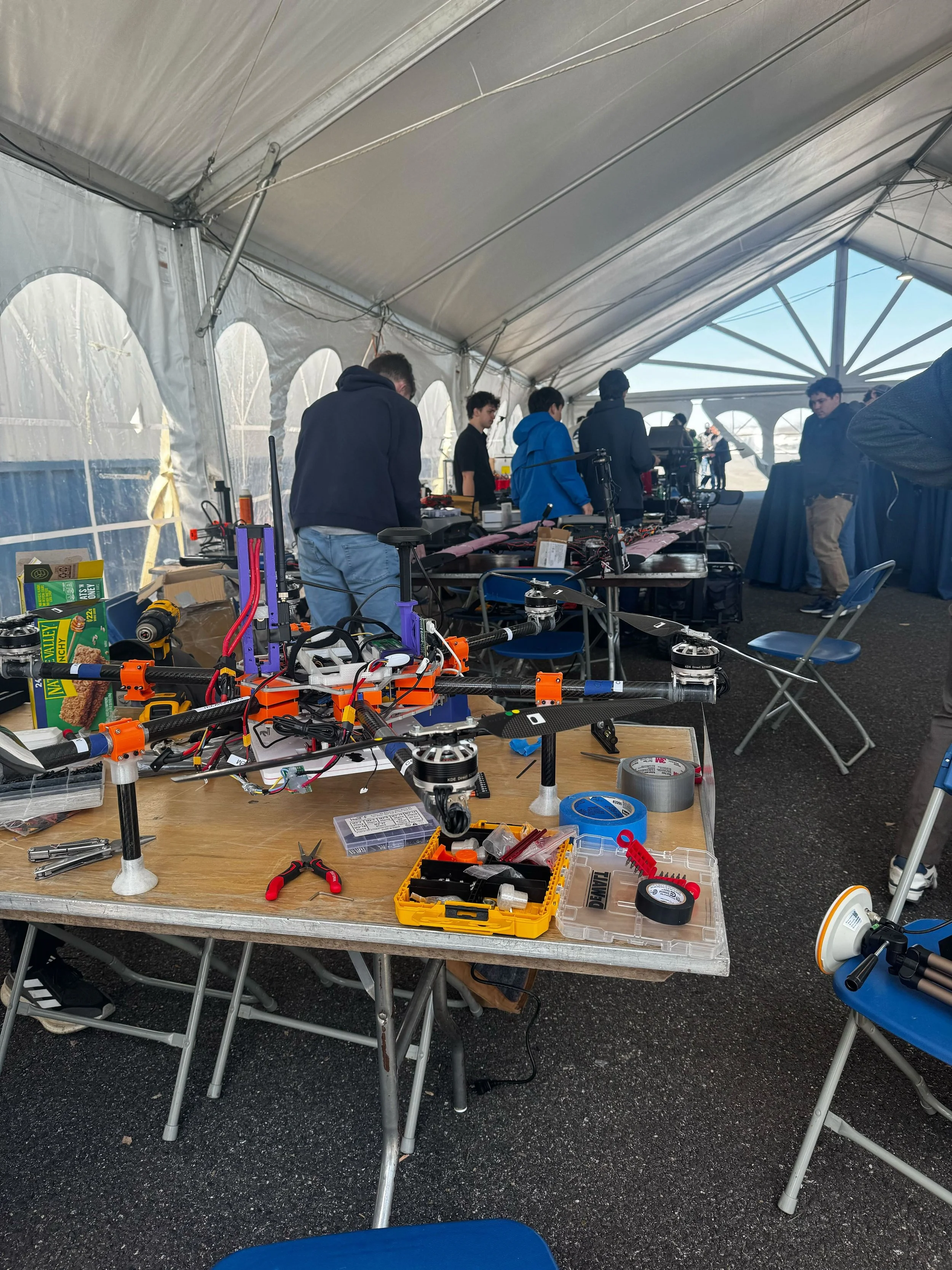
Picture of our hexacopter at competition.
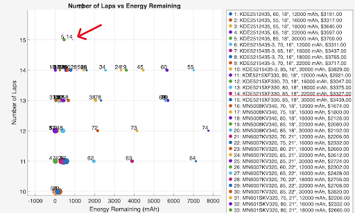
Mission model results showing each combination and its respective laps completed and energy remaining.
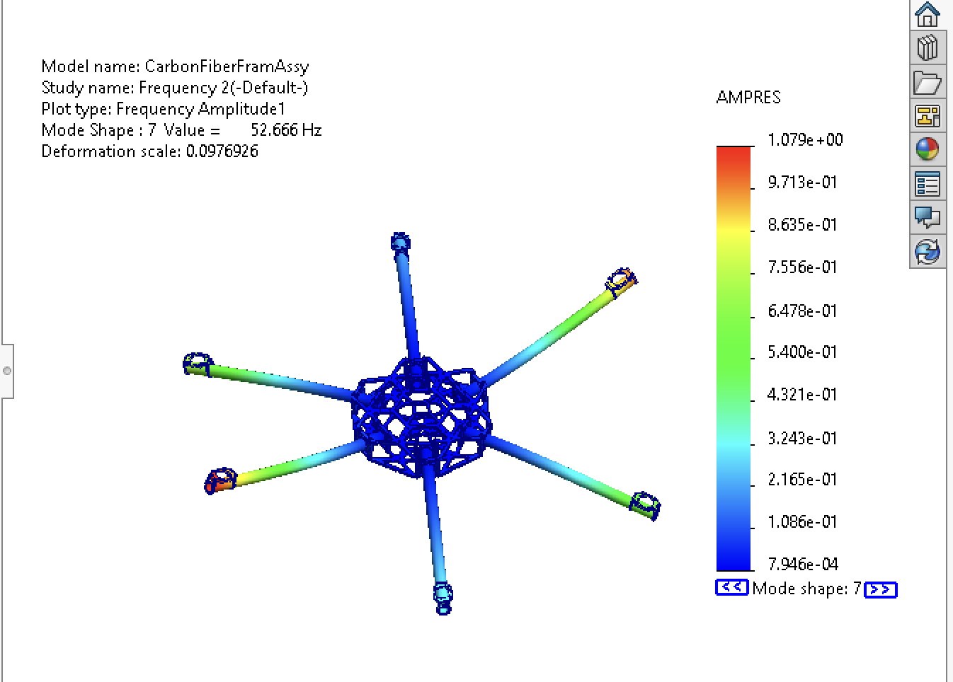
Natural frequency study with two 0.5" thick epoxied aluminum blocks.
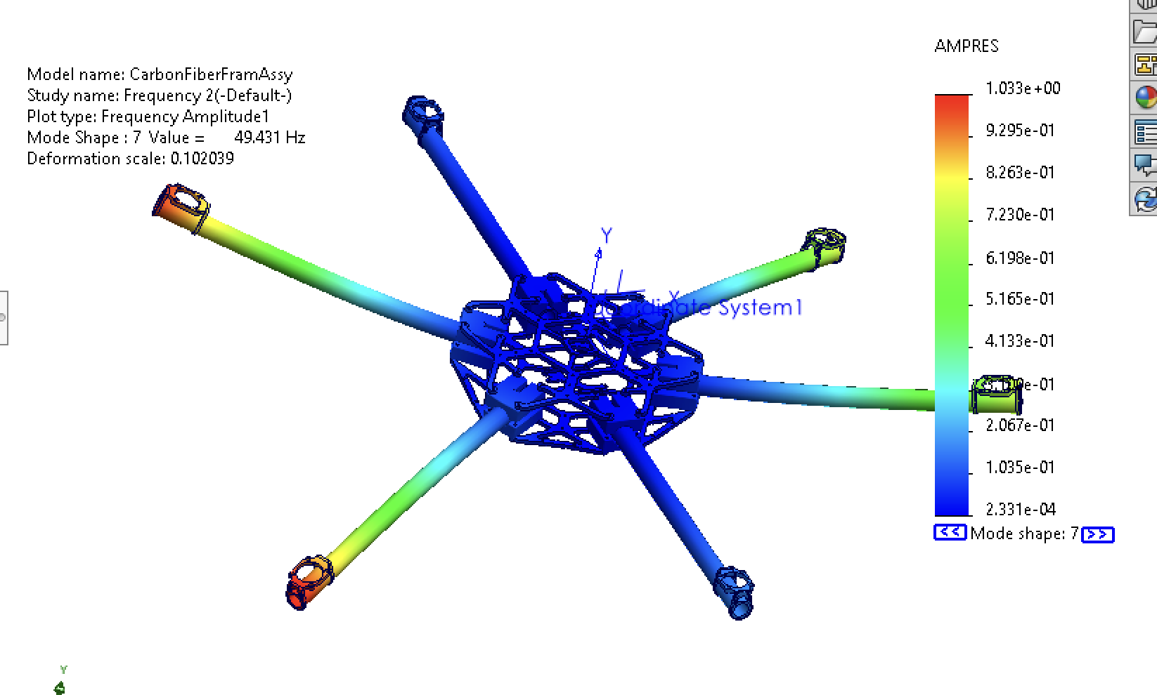
Frequency study with 1.77 inch thick PLA 3D printed arm clamps.
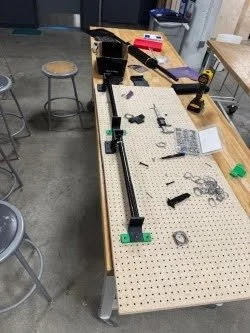
Epoxy jig used for attaching the motor mount rings.
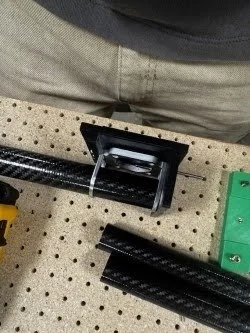
Close up of the motor mount rings and motor mount on the epoxy jig.
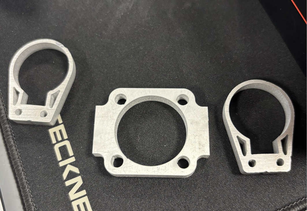
Motor mount plate and rings. Rings are fastened to the motor mount plate with 4 M3 screws.
Throughout the year while leading the general direction of the club, I was technically involved in developing our MATLAB mission model script, which finds optimal propulsion and battery combinations for our designated mission. Using a time-step based derivation method, the script walks through designated functions for takeoff, cruise, hover, and land. Thrust, weight, and drag are all modeled to find the acceleration of the aircraft at time steps. From this, integrating gets us the instantaneous velocity, which we can use to define drag in the equation. The script runs through laps of takeoff, cruise, hover, cruise back, and land to simulate our competition, and then optimizes throttle percentages for each motor-propeller combination.
Additionally, this year I expanded my knowledge in structural design and simulations for natural frequencies. In UAV design, it is critical for controllability to design structures far enough away from operational frequencies to ensure that structure oscillations do not interfere with control and command loops. In our case our motors would spin at 4200 rpm for hover and 7030 rpm as a maximum throttle, which correlates to 70 and 117.7 Hz respectively. Starting with a design with aluminum blocks epoxied into the carbon fiber arms, the first natural frequency was 52.6 Hz, which is 1.3x away from the lowest operational frequency of the motors. This follows the design principle of keeping natural frequencies at least 20% away from operational frequency.
For modularity, defining predictable failure modes, and testing the feasibility of 3D prints, I made a design with 3D printed clamps to replace the aluminum blocks. Given the large gap in stiffness between 3D prints and aluminum blocks, I ran the frequency study again, finding that the frequency only dropped to 49.4 Hz. With other design tradeoffs, I decided to pursue this clamp system, fine-tuning print settings to develop the final design.
In terms of manufacturing, our team primarily used water-jetting of 7075 aluminum for our motor mounts and frame, and interfacing with the carbon fiber arms. Motor mount rings are epoxied onto the carbon fiber tubes to create a rigid connection from motor to structures. These rings are fastened to the motor mount plate with M3 screws. Since the motor mounts are waterjet, the holes for the M3 screws required face milling operations, precision drilling M3 pilot holes into 4.8 mm thick material and tapping threads.